

Voltage Sag Mitigation: Grid-Fed Compensation vs. Energy Storage
Nov 18 /2026
Consider two three-phase disturbances, each lasting 0.5 seconds. In the first, the supply voltage falls to 70% of its nominal value. In the second, it drops to 0%, creating a short interruption. The duration is the same, but the available energy is very different: in the first event, the grid continues to supply power; in the second, a separate energy source is needed if the protected load must keep operating.
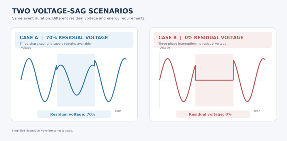 Figure 1. Two voltage-sag scenarios with the same event duration but different residual-voltage levels. Simplified illustrative waveforms; not to scale.
1. Grid-fed online compensation: using the remaining supply
In the 70% residual-voltage example, the incoming supply is weakened but not completely lost. A grid-fed INPAVC dynamic voltage restorer (DVR) is connected in series between the supply and sensitive loads. When it detects a voltage sag, it injects a compensating voltage so that the combination of the supply voltage and injected voltage can keep the load-side voltage within the required range. The compensation energy is drawn from the incoming supply, so no separate energy-storage unit is required.
Does any residual voltage guarantee successful compensation? No. The deeper the sag, the greater the voltage injection required, and the harder it may become to draw enough energy from the remaining supply. Whether a grid-fed system can cover a particular event depends on both the minimum residual voltage and the event duration, along with the connected load and the device's operating limits.
Therefore, a selection should be based on a measured sag profile—not simply whether the voltage was above zero. The recorded residual voltage and duration should be checked against the specific model's published mitigation envelope.
For INPOWER's online-type INPAVC, the specified capacity range is 100–3,000 kVA, with a rated voltage of AC 380 V. It offers a voltage sag mitigation option without a separate energy-storage unit, provided the event remains within the selected model's compensation capability. The minimum residual voltage and event duration must be checked against the applicable product specifications.
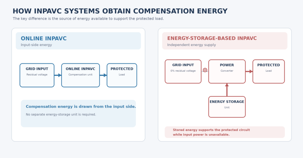 Figure 2. Energy paths in online and energy-storage-based INPAVC systems.
2. Energy-storage compensation: supporting a supply interruption
Now consider the event in which all three incoming phases fall to 0% residual voltage. With no usable input supply available during the interruption, a grid-fed compensator cannot draw the active energy required to maintain the protected load. If the process cannot tolerate an interruption, the system needs an independent energy source for the required ride-through period.
An energy-storage INPAVC combines a power converter with an energy-storage unit that can support the protected circuit when input voltage is lost. The product specifications list a minimum residual input voltage of 0%, a capacity range of 20–3,200 kVA, and rated voltage options of 210 V, 400 V, 480 V, and 690 V. The achievable support duration depends on the selected storage configuration and connected load; 0% residual-voltage capability does not, by itself, establish a guaranteed backup time.
Two separate questions govern selection: which loads must remain energized, and for how long? The first determines converter output capability; the second determines the required storage energy. Essential controls and auxiliary equipment may also need to remain powered, not just the primary production machine. The design must specify whether power is required until the utility recovers or until another source reliably takes over.
For example, semiconductor manufacturing equipment can be highly sensitive to brief voltage disturbances. An interruption may stop a process and lead to scrap or equipment downtime. For these applications, engineers should assess the full protected-load chain, the necessary ride-through period, and the installation, cabling, access, and maintenance requirements for both power-electronics and storage cabinets.
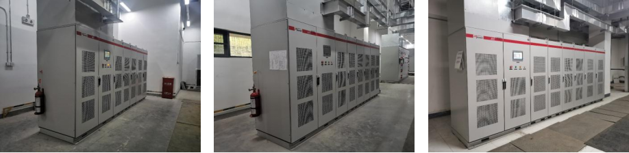
Figure 3. Installation views from the 300 kVA project. The source article identifies separate power and energy-storage cabinets but does not assign individual cabinet types to each photograph.
3. Selection depends on the entire disturbance profile
Both INPOWER online-type and energy-storage INPAVC systems specify a configurable response time of 1–5 ms. Response time describes how quickly the equipment initiates corrective action, while energy-support duration describes how long the protected load can be maintained during a disturbance. The required response time must be evaluated against the sensitivity of the load; for storage-backed systems, the required support duration must also be met. Both should be checked against the performance limits of the selected model.
Before choosing a solution, establish the lowest recorded residual voltage, disturbance duration, protected-load capacity, and the full set of equipment that must remain in service.
If enough residual supply remains and the event falls within the grid-fed model's compensation envelope, the online type may offer a route with less space and maintenance demand than a separate storage system. If protection must extend to a three-phase 0% interruption—or the grid-fed device cannot cover the required operating conditions—evaluate a storage-backed DVR and size its energy reserve for the required ride-through period.
A 0.5-second event cannot be evaluated by duration alone. The deciding factors are how far the voltage falls, how the system behaves during the event, and which loads must continue operating.
-
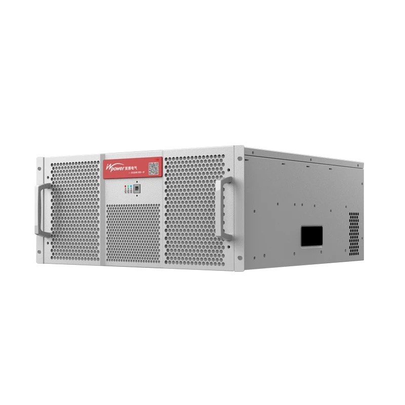
BLUEWAVE Active Power Filter
The BLUEWAVE 3-Level Active Power Filter utilizes advanced digital control and IGBT-based power electronics to monitor and neutralize harmonics in real time. By injecting an equal and opposite compensation current, it reduces harmonic distortion and improves current waveform quality in systems with nonlinear loads.
-
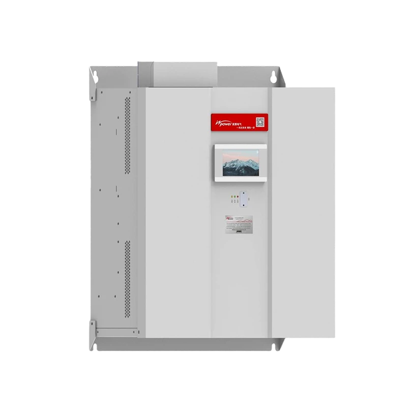
INPSVG LV Static Var Generator
The INPSVG is a dynamic reactive power compensation solution based on power electronics technology. It provides bidirectional and stepless reactive power regulation with fast response, maintaining stable power factor performance without over- or under-compensation.
-
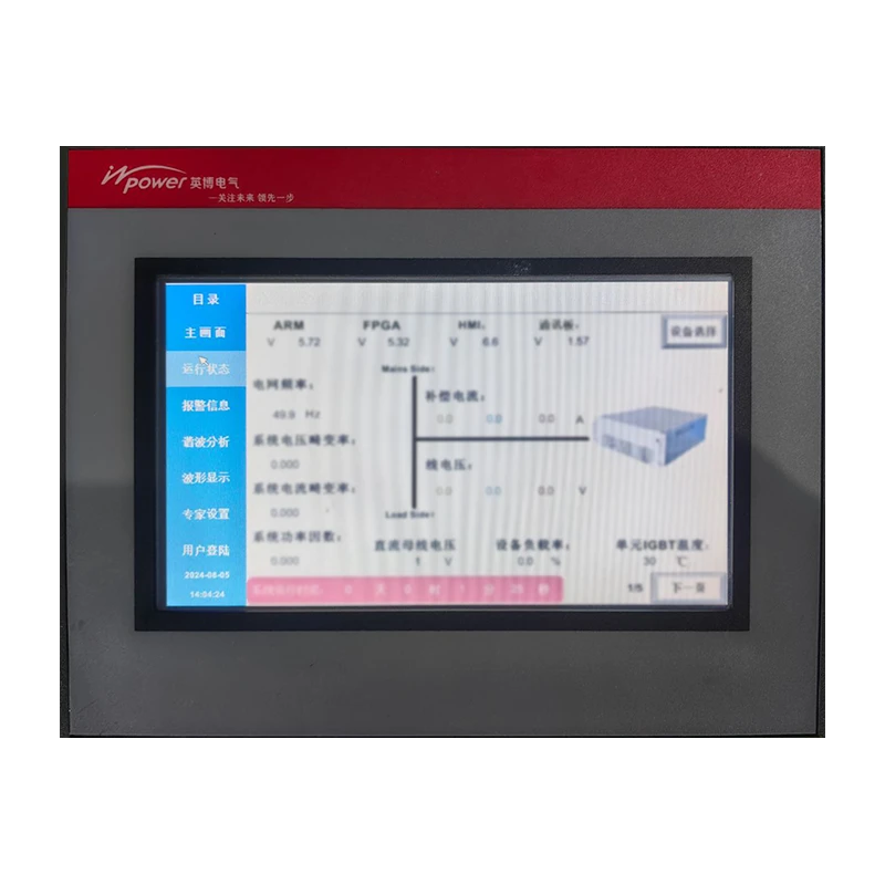
LSVG-2000 Dynamic Filtering and Compensation Controller
The LSVG-2000 Dynamic Filtering and Compensation Controller is designed for coordinated power quality management in active filtering and reactive power compensation systems. It enables unified control of APF and SVG units based on system operating conditions, helping improve power factor, reduce current harmonic distortion, and mitigate three-phase unbalance. The controller is suitable for industrial power systems requiring integrated monitoring and coordinated compensation.
-
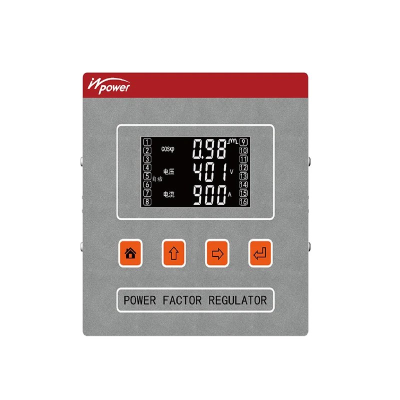
BKU Power Factor Controller
The BKU series is a high-performance reactive power compensation controller designed for low-voltage power systems from 0.20 kV to 0.75 kV. Powered by a 32-bit ARM processor, it provides precise reactive power control, stable operation, and efficient power factor improvement with a compact and reliable design.
-
Previous:
None
Latest News
-
Voltage Sag Mitigation: Grid-Fed Compensation vs. Energy Storage
Explore how online compensation and energy storage address voltage sags and maintain critical industrial loads.
-
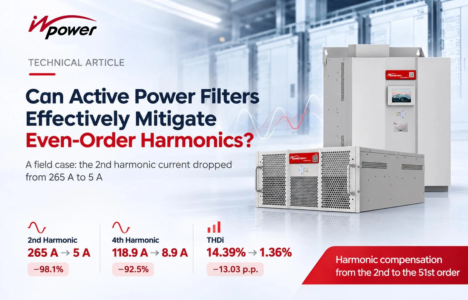
Can Active Power Filters Effectively Mitigate Even-Order Harmonics?
Can APFs effectively mitigate prominent 2nd and 4th harmonics?
-

Before Deploying 100 kW+ Racks: Reassess Your Power Quality Configuration
What should be reassessed when AI rack power increases?